Locations:

No significant differences related to instrumentation choice in 3-D CT preoperative planning
By Eric Ricchetti, MD, and Joseph Iannotti, MD, PhD
Advertisement
Cleveland Clinic is a non-profit academic medical center. Advertising on our site helps support our mission. We do not endorse non-Cleveland Clinic products or services. Policy
Glenoid component loosening is the most common long-term complication following anatomic total shoulder arthroplasty (TSA). Accurate placement of the glenoid component is expected to decrease component malposition and better correct pathologic deformity in order to decrease the risk of component failure over time. However, achieving this goal may be challenging due to difficulties in determining the degree of preoperative pathology that is present, determining the best implant for correction of this pathology, and correcting the pathology at the time of surgery.
Prior studies have demonstrated inaccurate glenoid component placement when using standard surgical instruments and two-dimensional (2-D) imaging without implant templating, particularly as the degree of glenoid deformity or bone loss worsens. In contrast, improved accuracy of glenoid component placement has been demonstrated using three-dimensional (3-D) computed tomography (CT) preoperative planning and patient specific instrumentation (PSI). However, studies comparing the use of different intraoperative tools are still lacking.
We sought to compare the accuracy of glenoid implant placement in primary, anatomic TSA when using 3-D CT preoperative planning with different types of standard and patient-specific instrumentation.
One-hundred seventy-three patients with end-stage glenohumeral arthritis undergoing primary, anatomic TSA were enrolled in three prospective clinical studies evaluating 3-D CT preoperative planning with implant templating and PSI. All patients underwent preoperative 3-D CT planning to determine optimal glenoid component and guide pin position based on surgeon preference. Patients were then placed into one of five instrument groups used for intraoperative guide pin placement: (1) standard instrumentation (SI); (2) SI combined with a 3-D glenoid bone model (BM) containing the guide pin; (3) BM combined with a single-use PSI; (4) BM combined with a reusable PSI; and (5) use of reusable PSI with an adjustable, reusable base (Figures 1-5). Postoperatively, all patients underwent a 3-D CT with metal-artifact reduction within four months of surgery to compare actual versus planned glenoid component position. Deviation from plan was assessed by component orientation (version and inclination in degrees) and location (anteroposterior and superoinferior position in millimeters) and was compared across groups based on absolute differences and outlier analysis. Univariable and multivariable comparisons were performed, with three major treatment groups evaluated and compared in the final analysis: Standard Instrumentation (Groups 1, 2) versus Single Use PSI (Group 3) versus Reusable PSI (Groups 4, 5).
Advertisement
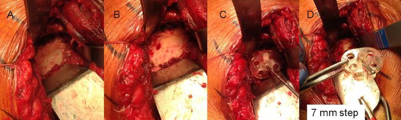
Image content: This image is available to view online.
View image online (https://assets.clevelandclinic.org/transform/b87bee46-b192-49cf-88a7-5f75b42ebce4/fig-1_png)
Figure 1: Intraoperative photographs of standard instrumentation (Group 1). Panel A shows a B2 glenoid with a paleoglenoid having some remaining soft tissue and the bone surface of the posterior neoglenoid. Panel B shows the soft tissue removed from the paleoglenoid and an anterior osteophyte. Panels C and D: A pin guide with a 7 mm posterior step is placed with the flat surface of the anterior portion of the pin guide resting on the paleoglenoid and the posterior step of the guide placed on the neoglenoid. This orients the guide pin slot of the guide to be in line with the planned location and orientation of the guide pin as defined by the preoperative plan. After the guide pin is placed through the guide, its location is verified with the pictures from the preoperative plan.
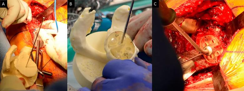
Image content: This image is available to view online.
View image online (https://assets.clevelandclinic.org/transform/62e0fcb8-997f-4717-aa47-687ed1bf02d9/figure-2_png)
Figure 2: Intraoperative photographs demonstrating use of a bone model for guide pin placement using standard instrumentation (Group 2). Panel A: A sterile bone model of the patient’s glenoid with the guide pin in the location and orientation from the preoperative plan. The location of the pin is marked on the glenoid surface based upon a visual inspection of the bone model. Panel B: A pin guide is placed onto the bone model over the guide pin so that the guide is perpendicular to the pin. In this case a flat backed pin guide (without augmentation) achieves that result. If there were posterior bone loss then the correct pin guide would be augmented, as shown in Figure 1. Panel C: The pin guide is removed from the bone model and placed in the same location and orientation on the glenoid surface, with the guide pin placed through the slot provided in the guide.
Advertisement
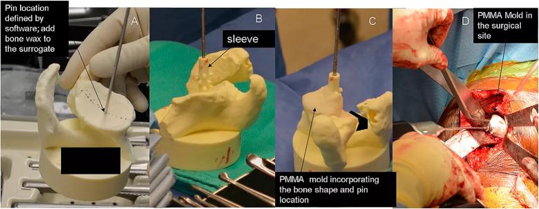
Image content: This image is available to view online.
View image online (https://assets.clevelandclinic.org/transform/99121180-fbd2-4b5b-9329-9c6ad8cec1b3/fig-3_png)
Figure 3: Intraoperative photographs demonstrating the use of a bone model and PMMA cement mold for guide pin placement (Group 3). Panel A: A sterile bone model containing the guide pin is compared to patient’s exposed glenoid surface. A thin layer of bone wax is placed onto the bone model in an area that is easily accessible on the glenoid surface and is best represented by the model. Panel B: A sleeve is placed over the guide pin. Panel C: PMMA bone cement in its late doughy stage is placed over the selected area of the bone model incorporating the sleeve. Panel D: Once the mold is hardened it is removed from the bone model and placed on the glenoid surface in the same location as the model and a guide pin is placed through the sleeve of the mold.
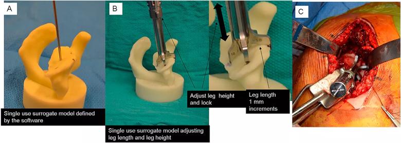
Image content: This image is available to view online.
View image online (https://assets.clevelandclinic.org/transform/37f68d9e-51e3-4693-b6e1-453fde99a1c9/fig-4_png)
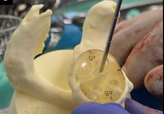
Figure 4: Intraoperative photographs demonstrating the setting of a reusable PSI tool using a bone model (Group 4). Panel A: A sterile bone model with guide pin is used. Marks are placed in specified locations on the bone model. Panel B: A reusable cannulated pin guide having five slots. A specified leg is placed in each slot. Each leg has a specified foot length. The cannulated handle is placed over the guide pin and each leg oriented over the specified mark on the bone model. The height of each leg is adjusted so that the foot contacts the bone model at each of the marked locations. This defines the height of the legs. The legs are locked into that location by turning a collet on the middle of the cannulated handle. Panel C: Once locked, the tool is removed from the bone model and placed onto the same location of the glenoid surface. The guide pin is placed through the cannulated handle into the bone. The location and orientation of the guide pin in the glenoid is verified by comparing it to the bone model.
Advertisement
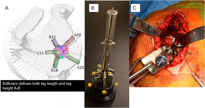
Image content: This image is available to view online.
View image online (https://assets.clevelandclinic.org/transform/7fea4a95-f504-4895-86e2-c68d62ccdafb/fig-5_png)
Figure 5: Preoperative and intraoperative photographs of the reusable PSI tool shown in Figure 4 used with an adjustable, reusable base. Panel A: A virtual model of the reusable PSI tool is placed within the 3-D CT preoperative planning software. The guide is placed over the guide pin in the software, the legs are selected for each slot and placed in the desired location on the bone within the software. The height of each leg is adjusted, within the software, to contact the virtual bone in the desired locations. The software then provides a height reading of each leg. Panel B: In the operating room, a sterile and adjustable base has five posts that are adjusted to specified heights and locked in place with brass thumb screws. The cannulated pin guide is then placed over the guide pin contained on the adjustable base. The legs of the pin guide contact each post and lock into position by turning the collet in the center of the handle. The pin guide is removed from the base and placed onto the glenoid surface as shown on the virtual model and a guide pin is placed through the handle into the bone. The location and orientation of the guide pin in the glenoid is verified with the pictures from the preoperative plan.
In nearly all comparisons, there were no significant differences in deviation from plan (absolute differences, outlier frequency) for glenoid component orientation or location across the three major treatment groups, with all of the treatment groups demonstrating improved accuracy when compared to historical controls that utilized 2-D CT imaging without implant templating and standard surgical instruments (Figure 6). The Reusable PSI group did show a significantly lower frequency of outliers for glenoid component version at the >10o threshold compared to the other two treatment groups on univariable analysis.
Advertisement
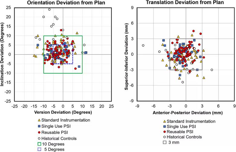
Image content: This image is available to view online.
View image online (https://assets.clevelandclinic.org/transform/5877ee86-89a2-42d2-a08e-a90f1d579dd5/fig-6_png)
Figure 6: Deviation from plan of the glenoid component in orientation (version and inclination in degrees) and location (anteroposterior and superoinferior position in millimeters). All of the patients represented by solid data points were treated with 3-D CT preoperative planning and implant templating. The yellow triangles are patients treated with Standard Instrumentation (Groups 1, 2), the blue squares are patients treated with the Single Use PSI (Group 3) and the red circles are patients treated with the Reusable PSI (Groups 4, 5). The open black circles are patients treated with standard instrumentation without 3-D CT preoperative planning and implant templating and represent historical controls.
This study did not demonstrate consistent differences in the accuracy of glenoid component placement in primary, anatomic TSA with regards to different standard and patient-specific instrumentation technologies when used in combination with 3-D CT preoperative planning for intraoperative guide pin placement. These results may suggest that the 3-D CT preoperative planning utilized in all of the treatment groups had the largest impact in improving accuracy of glenoid component placement in most cases, a finding noted in our prior study.
Surgeons have multiple standard and patient-specific instrumentation options available at the time of surgery for improving accuracy of glenoid implant placement when used in combination with 3-D CT preoperative planning. It should be the judgment of the surgeon based upon cost, time to delivery, and their experience to select the instrumentation that will best achieve the desired outcome.
Dr. Eric Ricchetti is Center Director for Shoulder Surgery and a shoulder surgeon in the Department of Orthopaedic Surgery and the Orthopaedic and Rheumatologic Institute. He can be reached at 216.445.6915 or ricchee@ccf.org.
Dr. Iannotti is Chief of Staff of Cleveland Clinic Florida and a shoulder surgeon in the Department of Orthopaedic Surgery and the Orthopaedic and Rheumatologic Institute. He can be reached at 954.659.6538 or iannotj@ccf.org.
Advertisement

How it’s similar but different from the direct anterior approach

Collaboration must cross borders and disciplines

Systematic review of MOON cohorts demonstrates a need for sex-specific rehab protocols

Should surgeons forgo posterior and lateral approaches?

How chiropractors can reduce unnecessary imaging, lower costs and ease the burden on primary care clinicians

Why shifting away from delayed repairs in high-risk athletes could prevent long-term instability and improve outcomes

Multidisciplinary care can make arthroplasty a safe option even for patients with low ejection fraction

Percutaneous stabilization can increase mobility without disrupting cancer treatment